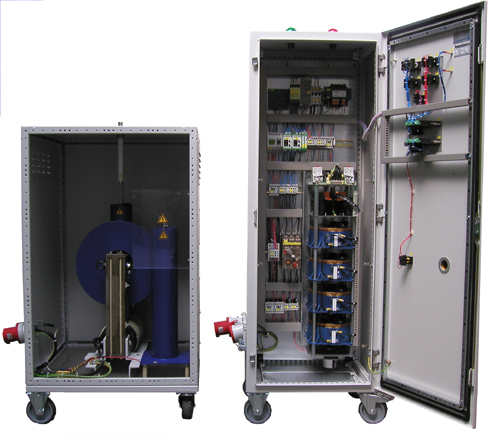
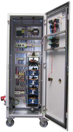
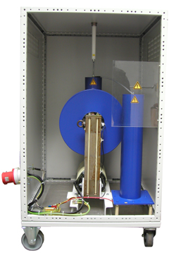
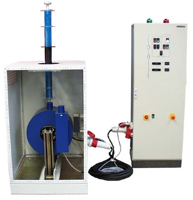
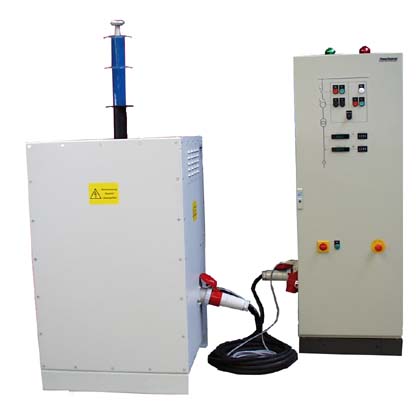
The units of ISO Series are high-voltage power supply according to customer requirements with variable voltage and current control and rollover counter. They were developed for
- destructive high voltage testing
- HV supply in research and Industry
- HV-conditioning of electronic components, especially components of the vacuum technology
In addition, the series is used for the monitored, dedicated operating
- Electrostatic precipitators and
- Flocking systems
There are placed on the manufacturing quality special requirements.
Vacuum components have the unpleasant tendency to lose by storage on dielectric strength. This increases for longer bearing components (starting at 3 months), the probability of error when first use exponentially. HV flashovers often lead to the complete destruction of this unused component, and possibly also the entire electronics in the environment.
For this reason, transmitting tubes, vacuum capacitors and similar vacuum components representing adjacent to the system itself has a significant value, tested before the direct use on site to high dielectric strength and are "conditioned". This procedure can be found as standard in radio and television broadcasting stations, but increasingly also on site at operators of industrial high-frequency equipment.
Based on years of experience in the field of high voltage technology in connection with the production technology for vacuum capacitors and transmitting tubes is the Fa. PowerSources been possible to develop an entirely new generation of high-voltage test systems. This is based on completely new measuring method with much more precise measurement technology, than previously used in manufacturing and service.
The device family will use in production, high-voltage testing and in service of the following components of the high-voltage and high-frequency technology:
- Vacuum capacitors
- Ceramic pipes, barrel and Disc Capacitors
- Foil and Mica Capacitors
- Variable Air Capacitors
- SF6 capacitors and switching elements
- High-frequency transmitting tubes
- Rectifier Tubes
- Vacuum interrupters
- Vacuum relay
- Audio tubes
- Assets u. Passive high-voltage components of all kinds
Through the newly developed test technology also significantly low health risk of the test personnel is given, than previously used AC sources:
- There are no X-rays more
- The energy of the new measurement procedure is extremely low, the specimen is optimally protected during the measurement
- A direct electric shock is unpleasant, but not deadly!
| Input Voltage | 3 x 400V |
| Loaded Phases | L1, L2 |
| Frequency | 50Hz |
| Input Current | 50A |
| Connection | 63A, CEE |
| Output Voltage | 0…50kV~, adjustable |
| Implementation | single-ended |
| Connector | to HV-Insulator |
| Output Current | max. 400mA |
| Output Power | max. 20kVA |
| Control | manually or automatically (SPS) |
| manually | Button for off, on, down, up with zero position forced shutdown in the adjustable maximum current is exceeded, limitation on adjustable maximum voltage limit specification 0 ... 50kV / 0 ... 400mA via potentiometer |
| automatically | Button for Stop, Start |
| Interlock | single, 230V~ |
| Warning Lights | red/green, 230V~/max. 100W |
| Programming | SPS, modifiable |
| Test cycle | automatic return to zero, power-up within 18 seconds on adjustable test voltage (max. 50 kV) after the test period (1min.) or exceeding the adjustable maximum current shutdown and return to zero |
| Interfaces | analog measurements (0 ... 10V =, corr. 50kV or 400mA) via BNC connectors |
| Dimensions | 600 x 500 x 1800 (control cabinet) 750 x 750 x 1400 (transformer cabinet) |
| Weight | approximately 220kg (control cabinet) / approximately 300kg (transformer cabinet) |
- Installation and electrical connection
Castors must always be forward and be locked! Connect the interlock connector X9 external monitoring contacts (maximum 2 NC) at or assemble the plug with corresponding bridges. At the terminals X7 / X8, you can connect additional external warning lights as needed. In addition are available at the BNC sockets X12 and X13 normalized 10V signals for output voltage and current available. About the RS-232 port, the current measured values can be read via software and detained for entering into a test report. The required basic software is included.
The test load must be connected to the high voltage output and the grounding bolt of the control panel. The ground should be done via a short cable with a sufficient cross-section.
The connection to the mains supply via the CEE connector X1. In correct phase L1-N is important! The recommended fuse is 16A. After performing this connection rules the device is ready for use.
- Control
About the selection switch hand cars can be selected if the drive controlled manually or is to run the automatic test program.
- Manual mode
About the button HAND/AUTO - the output voltage can be switched on and off and can be changed in height. After switching off not automatically rewinds to zero. The output voltage reaches the set limit value, a further increase is no longer possible. If the set current level is exceeded, the high voltage switches off automatically.
- Automatic operation
In automatic mode, first a return to zero. After that, the high voltage is turned on and ramped up to the set limit. Subsequently, the plant for the programmed test remains switched on (factory 12 seconds). After the test period, the high voltage switches off automatically and the variable transformer is moved back to the neutral position. If the set current value is exceeded, the high voltage is switched off immediately.
- Manual mode
- Software interface
The continuously supplied with the instrument measuring software detects the instantaneous voltage and current values. In addition, the maximum applied voltage and the corresponding current value with date, time and serial number of the check is displayed for each test cycle. (For this indicator, it is necessary that the output voltage exceeds a value of 1000 V.)
- Analog outputs
At the BNC connectors are 10V signals are available, which correspond to the instantaneous values of the output voltage and output current.

